Abstract : This paper describes the processing characteristics of titanium alloy parts, analyzes the CNC turning process of thin-walled titanium alloy parts, and introduces the CNC milling processing method and tool selection of thin-walled titanium alloy slits. Through the process analysis and tool selection of thin-walled titanium alloy parts, not only the dimensional and shape tolerances of the parts are ensured, but also the productivity is greatly improved, and it has certain engineering practice guiding significance in production practice.
1. Analysis of processing technology of titanium alloy sleeve
As shown in Fig. 1, a thin-walled titanium alloy part has a wall thickness of only 1.8 mm, a dimensional tolerance of the inner hole of 0.1 mm, and an inner and outer circle coaxiality requirement of φ0.05 mm, and is required to be processed on the circumference of the thin-walled sleeve. 36 slots with a width of 0.6mm and a length of 50mm. The part material is TC4. The surface roughness value Ra=1.6μm is required. It not only has high dimensional machining accuracy and shape tolerance requirements, but also requires low surface roughness. Processing is difficult.
Figure 1 Thin-walled titanium alloy parts
Titanium alloy materials have a wide range of applications in aerospace and other fields. The characteristics are as follows: 1 low thermal conductivity and high cutting temperature. Under the same conditions, the cutting temperature of TC4 is more than double that of 45 steel. 2 During the machining process, the contact length between the cutter and the chip is short, so that the cutting force on the unit contact area is increased, and the tool is easily chipped. 3 Since the cutting deformation coefficient of titanium alloy is close to 1, the sliding friction path of the chip on the rake face increases, and the tool wear speed increases. 4 It has large chemical activity, and it is easy to produce surface deterioration pollution layer on the processing surface, which makes the tissue uneven, seriously damages the tool, and has the phenomenon of chipping, chipping and peeling. 5 Due to the high affinity of the titanium alloy and the high cutting temperature, the sticking phenomenon is serious during cutting, which causes joint wear during the cutting process.
Since the surface roughness value of the thin-walled titanium alloy sleeve is Ra=1.6 μm, the requirement is high. At the same time, because it is a profile pipe material, its outer circle does not need to be processed, only polishing treatment is required. Therefore, to complete the processing of the thin-walled titanium alloy sleeve, five processing steps are required: 1 rough car inner hole. 2 Milling circumference 36 distribution grooves with a width of 0.6 mm and a length of 50 mm. 3 Remove the inner hole flanging burr. 4 fine car inner hole. 5 polished outer circle.
2. Roughing of the inner hole
Since the wall thickness of the thin-walled titanium alloy sleeve is only 1.8mm, the clamping scheme of the inner hole of the rough car selects the soft claw, as shown in Fig. 2, the welded copper soft claw, and the tail car has a 2mm limit. Position, limiting the positional movement of the thin-walled titanium alloy sleeve in the longitudinal direction.
Figure 2 Lathe soft claw
Because the YT type carbide turning tool has strong bonding force with titanium alloy material, it is easy to cause bond wear. Therefore, the tool of the rough hole is selected by YG8 carbide turning tool. The tool has a leading angle of 95° and a declination of 35°. Left and right, the front angle is 6°, the back angle is 9°, and the cutting parameters are: v=70 m/min, f=0.2 mm/r, ap=1 mm. Figure 3 shows the machining situation. After the roughing of the inner hole is completed, the finishing allowance is 0.15mm.
Figure 3 roughing
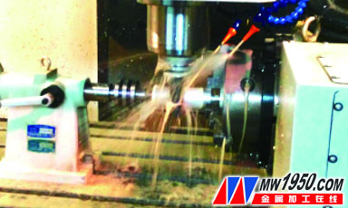
3. Processing of 36 grooves in the circumference
The processing of 36 grooves on the circumference of the thin-walled titanium alloy sleeve is selected on the four-axis vertical machining center, and the clamping head is passed through a clamping and clamping system, as shown in FIG. 4 . A mandrel 2 is required for clamping, and the outer circumference of one end of the mandrel is caught by the three-jaw self-centering chuck 3, and the outer end of the other end has a stop and the inner hole of the thin-walled titanium alloy sleeve 4 Cooperating, the matching clearance is 0.02mm, the inner hole of the other end of the thin-walled titanium alloy sleeve is matched with the outer circle gap of the plug 1, the matching gap is 0.02mm, and the center end of the other end end of the plug has a central hole through the live tip 5 Hold it up.
Figure 4 Schematic diagram of milling slot clamping
1. Plug 2. Mandrel 3. Three-jaw self-centering chuck 4. Thin-walled titanium alloy sleeve 5. Live top
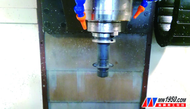
When the groove is machined, the groove width is narrowed due to stress concentration after thin wall deformation, so a saw blade cutter with a thickness slightly larger than the groove width should be used. Here, the cutter uses a high-speed steel saw blade cutter with a thickness of 0.7 mm, a bore diameter of 22 mm and an outer diameter of 60 mm. The number of teeth is 72 teeth, and the inner hole with a diameter of 22 mm is matched with the protruding shaft of the slot cutter. The matching clearance is 0.02mm, and Figure 5 shows the milling cutter.
Figure 5 milling cutter
The milling parameters are selected as follows: n=100r/min, f=25~30mm/min, ap=2mm. The amount of backing knife = the thickness of the saw blade, where the depth of the knife is ≥ the wall thickness of the thin wall sleeve is 1.8mm, because after the test, if it is not a single cut but a layered cut, due to stress concentration, the second feed will be The delamination causes the blade to chip or even break, and the processing efficiency is greatly reduced, so ap=2mm is selected here. It should be noted that when the saw blade milling cutter is fed radially along the titanium alloy sleeve, the backing knife amount ap ≥ thin wall sleeve wall thickness 1.8mm, do not layer milling, otherwise the cut thin wall sleeve is at the opening Due to the stress concentration, the opening will be deformed, resulting in a shrinkage. The second infeed saw blade cannot be smoothly fed into the blade, causing the saw blade to be chipped or broken, resulting in smooth processing. Figure 6 shows the processing live.

Figure 6 Milling groove processing
4. Removal of internal hole burrs
After the inner wall milling of the thin-walled titanium alloy sleeve is completed, since the titanium alloy has strong chemical affinity to the tool material and is easy to stick the knife, the milled burr is not easily broken, but is curled at both ends of the inner hole. As shown in Figure 7, it needs to be removed. The method used is to use a needle-nosed pliers to remove them one by one. Since the inner hole after the smashing is left with burrs that cannot be removed, the 0.15 mm finishing allowance left during roughing is removed just during finishing.
Figure 7 inner hole curling burr
5. Finishing of the inner hole
The inner hole finishing of the thin-walled titanium alloy sleeve is also a clamping scheme when rough machining is used, that is, the outer circle is clamped by the copper soft-packed claw, and the inner hole is refined by the inner hole precision cutter.
The inner hole precision turning tool selects the ceramic tool. The tool has a main declination of 95°, a secondary declination of 35°, a main rake angle of 8° and a rear corner of 12°. The cutting parameters were as follows: n = 400 r / min, v = 55 m / min, f = 0.15 mm / r, ap = 0.15 mm.
6. Polishing of the outer circle
Because the inner and outer round blanks of the thin-walled titanium alloy sleeve are relatively regular, the outer circle has reached the specified size requirement, so no separate processing is required, but the surface roughness is not ideal, and the outer circle polishing process is required.
The outer round polishing is also selected on the CNC lathe, through a three-claw self-centering chuck and a live top tip for a clamping solution. As shown in Fig. 8, one end of the mandrel is clamped on the three-jaw self-centering chuck, and the outer circumference of one end of the mandrel is matched with the inner hole of one end of the thin-walled titanium alloy sleeve, and the matching gap is 0.02 mm; thin-walled titanium The inner hole of the other end of the alloy sleeve is matched with the outer circle of the plug, and the matching gap is also 0.02 mm, and the live tip is matched with the center hole of the plug.
Figure 8 External polishing
When polishing, first coat a special polishing soap on the outer wall of the thin-walled titanium alloy sleeve (see Figure 9), then start the spindle. The spindle speed is n=500r/min, and the outer circle is polished by the polishing wheel.
Figure 9 Polishing soap
The finished parts are shown in Figure 10.
Figure 10 finished parts
7. Conclusion
Titanium alloy material is one of the typical difficult-to-machine materials. We need to combine theory with practice in practice, continuously accumulate processing experience, and develop practical titanium alloy processing technology solutions for specific problems. In this paper, the equipment, tools, fixtures, cutting parameters and other process methods for processing such parts are summarized, summarized and demonstrated, and applied in order to better guide the processing of titanium alloy in practice. The processing method in this paper may not be the best solution. Welcome peers to criticize and correct.


